Why Use a Timing Diagram Editor?
Timing diagrams can be drawn using pencil and paper, but this is time consuming and error prone. Each of the delays, setups and holds must be calculated manually, and even though the underlying math is easy it keeps you from focusing on the true problems of your circuit design. And the worst part, happens after your timing diagram has shown you an error in your design, when you must then either scrap the picture or start erasing and redrawing to incorporate the fix.
When you use a commercial timing diagram editor, you automatically get the redrawing features. Also most of the real engineering tools will calculate the min-max delay timing. Our favorite editors come from SynaptiCAD at www.syncad.com. Both the Timing Diagrammer Pro and WaveFormer Pro tools have full min-max timing calculations and advanced common delay removal. And, WaveFormer Pro comes with a logic simulator that lets you describe waveforms using Boolean and registered logic equations, which really saves a lot of time when initially drawing the diagram.
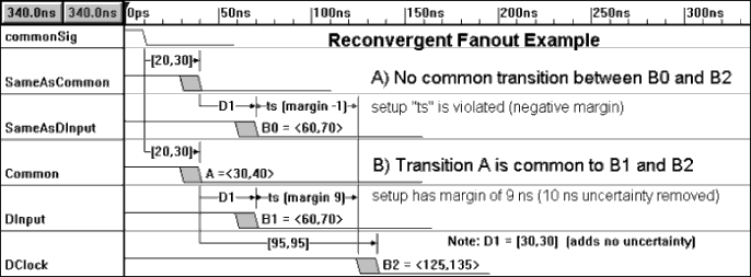
Common Delay Removal
The true power of a timing diagram comes from the ability to relate different signal transitions through timing parameters. Delays, setups, and holds are the three basic types of timing parameters. Other commonly used timing parameter types such as pulse width requirements can also be modeled using these three basic types.

Using Equations to Generate Waveforms
Sometimes a signal is an output of a digital logic circuit that is easily described using an equation, but would be a real pain to draw manually. Even simple circuits like a plain AND gate take some thought to get the output correct. But if you then buffer the signal with a common D-flip-flop the problem gets even more challenging. With the WaveFormer Pro timing diagram editor, you can just type in the equation and automatically see the results instantaneously. That product takes VHDL and Verilog syntax but also has some special syntax for handling min-max delays. Below are some examples of equations that WaveFormer accepts:
- Model a 3-input AND gate with a 20ns delay
- (SIG0 and SIG1 and SIG3) delay 20ns
- Model an AND gate with 2 different input delays
- (SIG0 delay 20ns) and (SIG1 delay 10ns)
- Model an AND gate with a delay between 15ns and 20ns. Here we use SynaptiCAD's syntax and use a delay parameter called GateDelay which has been defined to have a min time of 15ns and a max time of 20ns.
- (SIG0 and SIG1) delay GateDelay
- Multiplexers and Tristate Gates have to be modeled using C language conditional expressions in the form of conditional ? if_expr : else_expr
- Model a Tristate gate
- EnableSig ? SIG0 : 'bz
- Model a 2-1 Mux
- S0 ? SIG0 : SIG1
- Model a 4-1 Mux
- S1 ? (S0 ? SIG0 : SIG1) : (S0 ? SIG3 : SIG2)
- Multi-bit Equations are specified by setting the MSB and LSB of the signal (located at the bottom of the Signal Properties dialog). All register and latch operations support multi-bit signals.
- Concatenation of Signals is supported using the Verilog concatenation operator. You must set the MSB in the Signal Properties dialog to the proper size. If the size of the concatenated signal is larger than the receiving signal, then the most significant bits are dropped. Some examples of the concatenation operator:
- Signal Concatenation
- {SIG0, SIG1}
- Concatenation bit-slices
- {SIG[3:0], SIG1[7:4]}
- The tool can also take the output of the equation and send it into a register or latch. All the control settings and timing information of the memory element can be set in the signal's dialog.