Generating VHDL, Verilog, and SPICE testbenches from Timing Diagram Data
What happens when you are done with your design and timing diagram? If you have drawn it on paper, you usually have to junk that work and reenter the design into a simulator for further testing or in preparation for synthesis to an FPGA. This is unfortunate because the timing diagram of your circuit is also probably a pretty good test bench for the simulation of the same circuit. Most of the commercial timing diagram editors take advantage of this overlap by incorporating some kind of test bench translation into the products. Our favorite editor is WaveFormer Pro from SynaptiCAD which does VHDL, Verilog, SPICE, and a whole bunch of other formats. The best part is that the program has a Perl interface that lets the user tweak the output format if they want to.
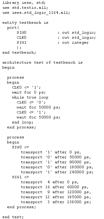
Before the timing diagram can be exported you should check the signal types and sizes. When drawing the timing diagram you can usually get useful timing analysis even if your types and sizes are not perfect. However, during code generation these must match yourVHDL and Verilog code exactly. Other then that check the actual code generation is just a trivial menu function and naming of a file. Below is an example of a timing diagram and the code that was generated from the image.

